Unified Modeling Language (UML)

What is Unified Modeling Language (UML)?
Unified Modeling Language (UML) is a standard notation for modeling real-world objects as a first step in designing an object-oriented system. Its notation is derived from and unifies the notations of three object-oriented design and analysis methodologies:
- Grady Booch's methodology for describing a set of objects and their relationships.
- James Rumbaugh's object-modeling technique for modeling and designing software.
- Ivar Jacobson's object-oriented software engineering and its use case modeling.
In 1994, Booch, Rumbaugh and Jacobson joined forces under the sponsorship of Rational Software, where they launched the original UML project. Soon, they were joined by others, and together, they integrated the three core methodologies, while also incorporating ideas from other sources.
In 1997, Object Management Group (OMG) adopted the UML standard and published version 1.1 in December of that year. OMG is also home to other notable standards, including Business Process Management Plus, Common Object Request Broker Architecture, MetaObject Facility and Information Exchange Framework.
In 2005, UML was accepted by the International Organization for Standardization as an official ISO standard, and it is now widely embraced by the technology community. The most recent release of the UML standard is version 2.5.1, which OMG published in December 2017.
Unified Modeling Language diagrams
The UML standard provides a methodology for creating diagrams that communicate the various aspects of a system's design. Project teams can use UML to share and discuss concepts, collaborate on the modeling process and design the final software.
The UML standard defines 14 types of diagrams, categorized as either structural or behavioral. The behavioral diagrams include a subset of diagrams referred to as the interaction diagrams. Figure 1 shows how the UML specification categorizes these diagrams into their respective groups.
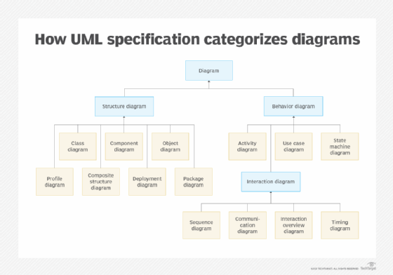
Structural diagrams represent the static structure of a system's entities. The diagrams are not concerned with time or dynamic behavior, but rather with the underlying entity structure and the relationships between those entities. The UML standard defines the following seven types of structural diagrams:
- Class. Diagram of the system's structure as determined by its classes, their attributes and methods, and the relationships between classes.
- Component. Diagram of the system's components, such as libraries and executables, and the relationships between those components.
- Object. Diagram of the system's class structure at a given point in time, thereby providing a snapshot of the class instances, their data structures and the relationships between those instances.
- Profile. Diagram of the how the system is extended through profiles, which include custom stereotypes, tagged values and constraints.
- Composite structure. Diagram of the internal structure of a class, its parts and connectors, and its interaction points, both within the class and with other classes.
- Deployment. Diagram of the distribution of a system's software artifacts across the physical hardware on which the artifacts will be deployed.
- Package. Diagram of the system's packages -- groupings of UML elements -- and the dependencies between them.
Behavioral diagrams are more concerned with the system's dynamic behavior. They take into account how entities change over time and interact with each other when carrying out an action. The UML standard defines three core behavioral diagrams:
- Activity. Activity diagrams outline the system's operational workflow, rendered in a flow chart that shows the activity carried out by the system's components.
- Use case. Use case diagrams address the system's functionality and how actors interact with the system, based on specific use cases.
- State machine. State machine diagrams cover an element's state during its lifetime as it participates in an activity, thus providing a dynamic model of its behavior.
The UML standard also defines a group of interaction diagrams that are a subset of the behavioral diagrams. The interaction subset includes the following four diagrams:
- Sequence. Diagram of the sequence of interactions between the objects participating in an activity in order to provide a mapping of their communication and message flow.
- Communication. Diagram of the collaboration between objects participating in an activity, similar to a sequence diagram, but focused more on the interactions themselves than on their sequence.
- Interaction overview. Diagram of the control flow of interactions between system entities, thereby providing a high-level view of complex interactions.
- Timing. Diagram of the sequence and timing of events within a given time frame, based on object behavior and interaction.
The UML standard does not specify how these diagrams should be created. It is concerned only with providing a universal syntax and structure for modeling system and business processes. As a result, there is no one acceptable approach to creating the diagrams, and a variety of approaches are being used. Team members might sketch them out on paper, draw them on whiteboards, create them in a draw program such as Microsoft Visio or use an online diagramming tool such as Gliffy.
Check out this intro to the five SOLID principles of object-oriented design, and read this overview of top software architecture visualization tools.